Bridges: linking together
03 May 2018
Challenges posed by the construction – and indeed maintenance – of bridges demand collaboration and are pushing contractors and equipment manufacturers to innovate in different ways.
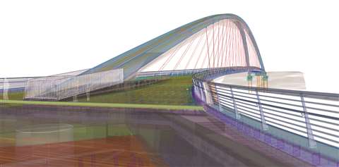
Building Information Modelling (BIM) was used from start to finish on the recent construction of the Grandfather’s Bridge in Helsinki, Finland, which has a span of 144.3m, a width of 4m, and a deck that is hung with 22 tension-rod pairs.
With the aim of achieving paperless design and construction, software company Tekla – owned by Trimble – created new practices for transferring BIM data from one project party to another. Tekla wanted to make its software easy for the contractor Kreate to use, since the firm was new to using the technology.
Aki Kopra, project engineer at Kreate, said, “In the bidding phase of this project, the Building Information Model was an official and binding document. I think that this type of method is becoming more common, but for me this was the first project in which we had a fixed model to support our estimation calculation during the bidding phase.”
By streamlining the bridge’s planning process, BIM helped to avoid errors further down the line, reulting in savings.
Jarkko Savolainen, building information specialist at A-Insinöörit Oy, the project’s BIM consultants, said, “The planning process is easier and clearer with BIM. It also provides more transparency for all the different parties of the project. BIM allowed the site crew to see and understand the structure of the bridge. This makes planning work, as well as the entire project, more fluent, quicker and flawless.”
BIM was used not only for the design of the Grandfather’s Bridge, but also for setting up schedules and monitoring and supporting the fabrication and erection of various elements. The status of the steel structures, for example, was broken down into three phases for scheduling: design, fabrication and installation.
This facilitated fluid collaboration between the construction site and fabrication operations because the workshop that manufactured the steel structures was connected to the model and its schedules were synchronised.
The project parties chose Tekla Model Sharing to access the combined model, meaning that everyone involved was able to use a constantly updated model. This included the client, the City of Helsinki, who could be shown visualisations of the project as it progressed.
Collaboration is a common theme of such large-scale projects as bridges. Denmark-based Ramboll has been called upon to provide support for the construction of a 21.8km-long sea bridge in India.
Set to be the longest sea bridge in the country and costing an estimated $2.2 billion, the Mumbai Trans Harbour Link will connect Mumbai and the satellite city Navi Mumbai, a planned township of Mumbai off the west coast of the Indian state of Maharashtra. Ramboll has signed a contract to provide design services and technical support during the construction process. It will be acting as advisor for the Indian and South Korean joint venture Tata Projects-Daewoo.
In its first year of operation, it has been estimated that 62,000 cars will use the bridge every day. This number is projected to increase to about 200,000 over the next 30 years of operation, assuming the Navi Mumbai International Airport becomes operational in that time.
Lars Thorbek, global division director for major crossings at Ramboll, said, “We are counting strongly on bridges and tunnels. We expect revenue to increase by 35% globally by the end of 2020 – in a market that is expected to grow by just under 6% in the same period. The North American, Scandinavian and German markets are expected to be particularly favourable.”
Meeting new demands
Growing amounts of traffic have also led to a major – and complicated – bridge project in Germany. Hochtief PPP Solutions is working in partnership with DIF, BUNTE, and lead contractor ViA6West to completely replace the Neckar viaduct at Heilbronn, as part of a €1.3 billion (US$1.6 billion) expansion of the A6 motorway between Weinsberger junction and Wiesloch/Rauenberg.
Although the existing 1.3km-long bridge – built in the 1960s – was renovated in 2003 at a cost of €17 million (US$20.9 million), it is struggling to cope with the amount of traffic; it is now used by approximately 100,000 vehicles every day.
The plan is to construct a new six-lane bridge over the Neckar valley. However, Gerald Hauke of ViA6West said, “A change to the route taken by the motorway and thus an overlap of old and new parts in the area of the abutments and connecting structures would involve immense extra costs.” As a result, a temporary bridge is being constructed alongside the old bridge, for redirected traffic, before the old bridge is dismantled and the new bridge is built.
The temporary bridge is being constructed in two sections – the foreland bridge, which is being launched with a launching girder, and the section over the Neckar valley, for which an incremental launching method will be used. The two sections will meet and be connected near the Neckar island.
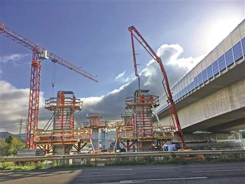
Once the temporary bridge is completed, the existing bridge will be demolished, and the foundations and piers for the new one will be created. These will be poured using Meva’s Mammut 350 formwork system and will require a special formwork solution that Meva planned using a 3D computer program.
Then, in 2022, 40 hydraulic cylinders regulated by a computer- and camera-controlled system will be used to move the deck of the temporary bridge laterally onto the new piers, positioning it with millimetre accuracy to complete the new bridge.
ViA6West will be responsible for the operation and maintenance of the viaduct until the end of 2046.
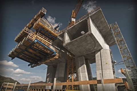
A pair of bridges are also under construction in Slovakia. The twin bridges – one for each direction of travel – will form a flyover at kilometre 7,500 of the D3 motorway, straddling Route I/18 and the Hričov reservoir.
The 1.5km-long bridge will be composed of span lengths that range from 30.5 to 110m in length. The central spans over the River Vah are being formed by a box girder with a variable depth of between three and six metres, segmentally cast in symmetrical cantilevers.
The remaining spans will have a double-tee cross-section, with a constant depth of three metres. They are being cast one at a time on stationary or mobile scaffolding. In this instance, the cross-section is being formed by a twin-T girder with a constant height, partly joined to the box girder with a variable height.
Doka is responsible for delivering the formwork for the two bridges’ foundations, piers and superstructures. To meet with the project’s tight deadline, the Austrian-based company supplied four pairs of its Cantilever Forming Travellers, Top50 large-area formwork, Staxo 100 load-bearing towers, and Doka 250 stair towers.
Again, collaboration has been key, with local structural engineers, Doka’s subsidiary Ceská Doka, and the Global Expertise Center Infrastructure in Amstetten, Austria, working together to make the handling and modification of the formwork traveler easier.
Bridge maintenance
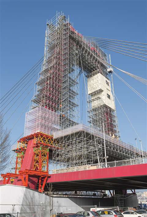
Peri formwork being used on the Williams Bridge
As the idiom about the painting the Forth Bridge suggests (a job so big that by the time you get to the end you have to start at the beginning again), bridges can be challenging structures to maintain once completed.
This is true of the cable-stayed Williams Bridge in the centre of Rotterdam in the Netherlands, which recently needed refurbishment work to be carried out on its two 60m-high pylons. It was said to be one of the most difficult scaffolding projects ever carried out in the Netherlands.
Since the bridge is an important link between the northern and southern parts of the city, it was required by the Municipality of Rotterdam that traffic not be impeded by the works. So, to avoid resting the 200-tonne scaffolding structure on the carriageway, a project-specific scaffold solution was designed by Peri – in collaboration with scaffolding specialists from Steigerbouw Van der Panne – which combined two of Peri’s existing systems – Peri Up and Variokit.
To begin with, truss girders had to be assembled across the carriageway in a single night. The girder package was pre-assembled at Peri’s facility in Schijndel and then the 21m-long girders were transported to the site on heavy-duty trucks. A mobile crane raised the girders onto the VST heavy-duty towers positioned on the sides of the bridge, as well as on the shoring and working scaffold temporarily erected in the middle of the bridge.
The LGS Lattice Girder System from the Peri Up Modular Scaffolding Kit was also used for scaffolding the pylon legs, enabling the creation of a projecting 10m protective roof on both sides. It also allowed a 12m working platform to be installed between the pylon legs.
To prevent materials from falling onto the road or into the River Mass, the Peri Up Flex Working Scaffold was enclosed with a shrink foil, which required anchoring to deal with the high winds that blow in from the North Sea.