Ropes and winches: Winding it on
23 November 2020
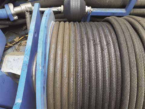
A common issue with wire rope on a winch drum is incorrect tension, especially on the bottom layer of multiple layer drums.
It is well known in the lifting industry that Lebus makes spooling systems for multiple layers of wire rope on winches and hoists. After all, the company invented the Lebus Counterbalanced Spooling System, explains Cris Seidenather, consultant director at Lebus International Engineers in Germany.

With patents long since expired, others are now free to copy the geometry of the Lebus grooved winch drum, but Seidenather likes to think that decades of knowhow gives Lebus an edge.
“What is less well known is that Lebus International Engineers does not just design, manufacture and (where requested) install spooling systems; a significant part of our activity is our consultancy work – troubleshooting, as often as not.
“We are thus well placed to see the recurring problems that users of lifting equipment frequently encounter with their crane ropes.”
Tighten the bottom layer
One of the most common causes of problems is running tight lines over a loose bottom line. If the rope is not spooled onto the drum under adequate tension at the outset, the bottom layer of the drum is unable to defend itself from the downward force exerted by the upper layers.
The fact is, that the lower the base tension on the bottom layer, seldom removed and rewound, the shorter the lifespan of the rope.
Lebus was called to join a meeting recently at an equipment manufacturer whose customers in countries as far apart as Canada, Portugal and Australia were all reporting visible rope damage, starting right after the safety turns of the first layer.
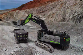
The equipment in this case was drilling rigs, but the principle applies equally to tower cranes.
When a drill rig starts to drill, not much of the rope on the drum is being fed out. But as the hole gets deeper, more rope is being spooled off and back onto the drum, just as with a tower crane that climbs in height with the progress of a tall building under construction. Although one is going up and the other down, the effect is the same. By re-spooling rope with a heavy weight on the end of it – in the case of the drill rig, an auger full of rock or earth – the outer layers of rope on the drum are spooled under tension, crushing the too-slack bottom layer that has yet to leave the drum.
There is no cure but prevention is simple. When spooling wire rope in multiple layers it is essential always to ensure that the first spooling is conducted when the rope is under tension.
Just like the strongman at the circus, who can withstand mighty punches to his midriff by tensing his belly muscles, a wire rope under tension can withstand extraordinary pressure when tense, but is vulnerable when it is relaxed.
Users sometimes think that they can solve this problem by using a pressure roller or rope press for first installation. But this does not tension the rope. The pressure roller simply applies a force perpendicular to the surface of the rope strands, pushing the rope downwards on to the drum to keep it in the correct groove.
Pressure does not tension or tighten the rope; only tensioning tightens a rope – acting from end to end rather than across the diameter – compacting it and stabilising it against external pressure.
In fact a pressure roller, if not adjusted correctly, could actually do more harm than good because pushing on a rope can cause it to go slack.
Wire rope is a complex organism that needs to be trained like a muscle. Whatever its construction – whether compacted or non-compacted, rotation resistant or not – a brand new wire rope straight from the manufacturer – is not yet at its best. It only reaches peak fitness after it has been spooled under tension around a drum a couple of times. Only then do the individual wires within the structure settle into their final position. With correct tensioning, the bottom layer will thus resist all the pounding and beating that upper layers will impose on it. A limp bottom layer will be swiftly beaten. The rope will inflict harm upon itself, effectively committing suicide. The tensioned outer rope is unharmed but the untrained rope below is worn out by continuous contact-grinding.
Parallel lines
The Lebus systems is sometimes called the parallel groove system because of the geometry of the groove. On a helix groove drum, the groove is at an angle to the drum flange, resembling the threads of a screw. On a Lebus drum the groove remains parallel to the flanges except for two crossover points on opposite faces of the drum to move the rope along the face and (when it reaches the flange) up on to the next layer.
It is at these crossover points that an untrained rope is vulnerable. This is where the wear process will primarily take, where the rope, its strands and wires are exposed to extreme high pressures when crossing from one parallel section to the next, twice per circumference.
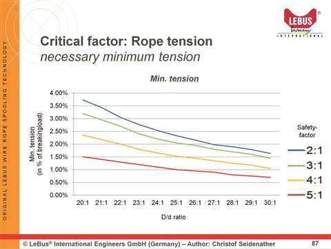
That leaves just one question: what is the correct tension for first installation of a wire rope into a drum? Well, that depends on two things: the required safety factor, and the D/d ratio. D/d is the ratio of the diameter (D) of the drum divided by the diameter (d) of the rope. The smaller the drum diameter (relative to the rope diameter) and the lower the required safety factor, then the greater the initial tension required when first spooling the rope onto the drum.
The graph illustrates what Lebus regards as best practice.
Wire rope elsewhere
Wire rope is a big part of suspension bridges as well as the equipment used in their construction. The 1915 Çanakkale Suspension Bridge under construction in Turkey will be the longest suspension bridge in the world. It is in the Çanakkale Province in northwestern Turkey and is due to be completed in 2022.
To take the record the main span of 2,023 metres will surpass the Akashi Kaikyo Bridge in Japan by 32 metres.
UK-headquartered DLT Engineering is the subcontractor for the design and supply of eight 450 tonne capacity main deck lifting gantries, the system of PPWS cable erection winches and rollers, eight cable compaction machines and eight cable wrapping machines. DLT’s scope of work also includes on site supervision and maintenance of all the above menrtioned systems.
For erection of the steel pylon sections DLT also supplied 4 x 60 tonne capacity hydraulic sling length adjustment systems.
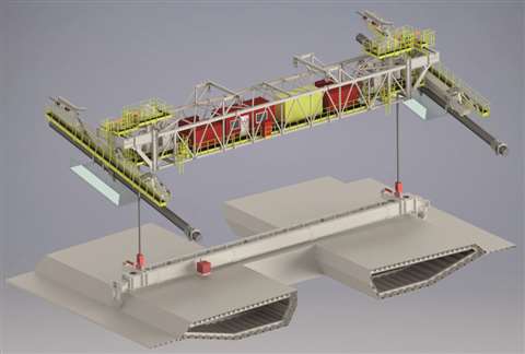
One of eight 450 tonne capacity main deck lifting gantries to be supplied by DLT