A digital framework for falsework and formwork
20 August 2018
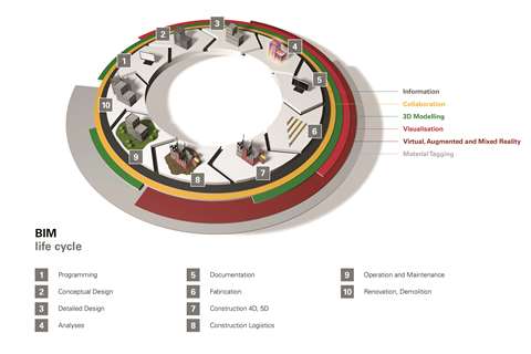
Advances in digital technology have been driving a trend towards total site solutions as data is brought together from all corners of a construction site and beyond. Building Information Modelling (BIM) offers a way of co-ordinating information about a new construction, right through from planning and design to production and even maintenance after completion. This holistic approach is having as much of an effect on providers of falsework and formwork solutions as it is on any other player in the industry.
With clients and contractors demanding greater visibility, UK-based RMD Kwikform said that it now had a greater responsibility to interact more closely with the entire supply chain, right from the point of design. Customers are now demanding IFC (Industry Foundation Classes) BIM-compliant models of the company’s temporary solutions.
Simon Dowd, major project manager at RMD Kwikform, said, “We recognised some years back that the industry would move away from 2D drawings. It has been a slow trend, but as we work closer with customers – particularly on larger infrastructure projects – it’s clear that 3D drawings should now be standard practice.”
3D capabilities
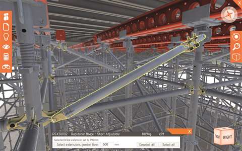
RMD Kwikform has since developed its 3D capabilities and created a visualisation tool called LocusEye that automatically renders 3D models. A given model can be changed in real time and viewed on a PC, tablet or smartphone, making it accessible to disparate parties involved in a project.
Dowd added, “Through this system, on-site clashes can be detected, plus data can be captured to better manage equipment and plan construction phasing.”
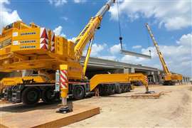
LocusEye was recently used to provide a quick response constructing the Astmoor Approach Viaduct as part of the Mersey Gateway Crossing in the UK.
The main contractor responsible for the project, Mersey Link CIV, commissioned RMD Kwikform to provide a solution to support the 115-tonne pre-cast concrete beams. However, the contractor needed to build a 40m span each week, meaning that RMD Kwikform only had seven days from initial contact to produce the design and begin delivering equipment to the site, so LocusEye played an important role by speeding up the process.
Megashor and Rapidshor propping systems were used to support the pre-cast beams situated at each 40m span. Since the site was on an exposed riverside, the solution had to make the most out of the permanent structure in order to withstand high wind loads.
The company’s engineering director Ian Fryer said, “On the outside of the composite assembly, the pre-cast beams are landed directly onto Megashor supports, which subsequently also support the bulk of the deck construction. The Megashor is laterally supported in one axis by Megashor yokes that clamp around the piers.
“Between the piers, Rapidshor falsework supports the Megashor yokes and the cast in-situ crosshead, as well as providing a boarded access from which the pre-assembled Megashor falsework could be safely erected and attached.”
Due to the sheer scale of the project and the volume of equipment required at such short notice, RMD Kwikform called on its national branch network to supply materials and equipment, which was sourced from across the UK.
Digital transformation
In recognition of the increasingly important role of digital technology in the construction industry, German-based Peri founded a Digital Transformation Office in 2017. The company’s digitalisation-related strategic activities and initiatives are grouped together and co-ordinated at the site, and Peri’s BIM Competence Centre has been integrated into it.
Daniel Stadel, head of the new office, said, “With the organisational change, we are taking account of the strategic importance BIM already has for the entire Peri Group and our customers today, as well as in the upcoming years.”
Peri currently offers a range of digital applications, from product-related apps for simple calculations and formwork & falsework systems to its online customer portal myPERI, which is an information platform designed to support the process.
An example of the software solutions provided by the company is PERIpath, which provides a full picture of a construction site, including the movement of materials, the erecting and dismantling of temporary structures, and the number of works on site. This was said to facilitate more efficient site management, as well as the provision of reports and detailed cost overviews to customers.
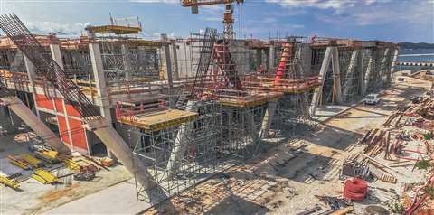
One large project that Peri’s subsidiary Peri Croatia recently supplied a falsework and formwork solution for was the new two-storey terminal building at Gazenica Passenger Port near Zadar, Croatia.
The challenge posed by the design’s complex geometry and the need for support at large heights was made greater by the stringent demand for occupational safety and high quality of the finished surfaces.
The most technically difficult design element was said to be the V-shaped, 10.3m-high circular columns. They required a customised Peri SRS Circular Column Formwork, and in order to support the first 6m-high concreting section, SRU Steel Walers and Heavy-Duty Spindles had to be adapted from the Variokit Engineering Construction Kit.
For concreting the second section, the team installed a working platform supported by Peri Up Flex Shoring that could be adapted to accommodate the diagonal circular columns. Peri Up Flex Stairs served as a safe and secure access solution, according to the company.
The building will cover an area of 25,000m2 in total, and after completion ships with a length of more than 400m will be able to dock at the port.
Nuances of modelling
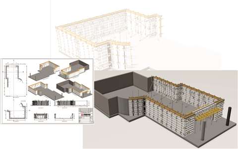
Talking about the nuances of creating BIM models for falsework and formwork projects, Tobias Wallner, head of IT engineering services at Germany-based Meva, said, “We differentiate between temporary and build-in parts. As the temporary components are only required for the production process of a building, these do not have to be archived in BIM in the long-term. The situation is different, however, for build-in parts such as anchor plates for climbing formwork systems, which constitute an integral part of the building model.”
In practice, Wallner said it had proved advantageous to think in terms of discipline-specific models, so the company develops formwork models that consist solely of formwork objects with formwork- and manufacturer-specific information.
Wallner said, “To ensure that model-based formwork planning works sensibly, the information in the building model must be complete – and it must be specified.”
This means that all in-situ concrete and steel-reinforced concrete parts, as well as installation surfaces and build-in parts, must be specified and classified in terms of building stages, storeys and building cycles.
Time is taken into account indirectly in the cycle definition and the manufacturing sequence in what is referred to as the shell construction model.
One significant benefit highlighted by Wallner was, “The planning processes become significantly more efficient due to the fact that the formwork supplier no longer needs to gather information.”
Since the model is available to everyone involved, suppliers can synchronise their schedule with everyone else’s without having to develop a separate model.
However, Wallner went on to say, “Digitalisation in the construction industry is far more than just the introduction of a new tool. On the contrary, BIM is part of a change process and requires a new way of thinking.”
In the constantly changing world of BIM, Meva needs to continually adapt its formwork object library. To this end, the company works with cloud-based solutions so that it can react quickly and comprehensively to any changes.
“This ensures that all persons involved in the planning process can not only access the latest data on the spot but also from anywhere in the world,” said Wallner.
Tricky geometry
Ulma recently used BIM for the restoration of the Ágora building of the Palace of Sciences and Arts in Valencia, Spain, which has an unusual elliptical geometry.
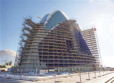
The entire building was covered with multidirectional BRIO scaffolding to refurbish more than 4,247m2 of space, both externally and internally.
BIM technology was used to help the various collaborators involved in the project to interact effectively. It allowed Ulma to plan each section and register them all in a single place that was accessible to all parties.
For the north and south ends of the building, BRIO Perimeter scaffolding with one-metre cantilevered extensions was used to reach a maximum height of 33m and cover a total surface area of 1,000m2.
For the four central phases of the building, which stretch to a height of 48m and have a surface area of 2,600m2, the same BRIO Perimeter scaffolding was used but with cantilevers that extended up to 3m and push-pull props that were adjusted to adapt the scaffolding precisely to the building’s varied curvature.
Sweet spot
Another project was carried out recently by Layher at a sugar factory in Sweden. A concrete silo with a height of 69m and a capacity of up to 80,000 tonnes of sugar was built by German contractor Heitkamp Bauservice using the slip-form method.
The silo wall grew at a rate of 2.5m per day, but a particularly challenging part was the roof structure, which consisted of roof rafters and a steel compression ring as the top closure element at a height of 63m. When the individual components were not forming a closed structure, the 45-tonne mass required high-strength support.
Applications engineers from Layher helped to plan a solution using the company’s software LayPLAN, which includes a CAD module. This plug-in for Autodesk AutoCAD can be used to create 3D designs of all types of scaffolding structures.
The solution in this scenario included three of Layher’s systems – Allround Scaffolding Lightweight, Allround Shoring Frames TG 60 and pre-assembled Allround Shoring Towers TG 50.