Falsework & Formwork: Taking new forms
06 November 2018
As buildings grow ever taller, bridges ever bigger and designs ever more complex, these impressive projects rely upon increasingly sophisticated falsework and formwork solutions.
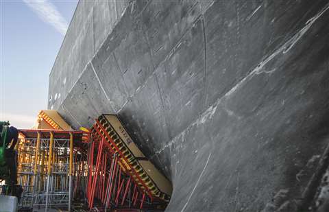
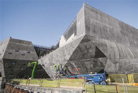
One notable example is the V&A Museum in Dundee, UK, the design of which was inspired by cliffs of sedimentary rock standing proud against the sea. It stands at the centre of the city’s £1 billion (€1.13 billion) waterfront regeneration scheme.
The £80.11 million (€90.8 million) building combines complex concrete architecture with glass facades and linear concrete cladding. Peri was appointed by Carey’s Civil Engineering to provide engineering services and bespoke formwork solutions.
Before the main construction began, a full-size sample panel with reverse curvature and slope was constructed on site. This was done to demonstrate buildability, wall geometry, surface finish and colour matching with the specialist lining material being used.
Peri worked to a 3D design model developed by structural engineer specialist Arup. By working with 3D drawings, Peri said it was easier to gauge the amount of structural support required to facilitate the build. In fact, it was suggested that it would have been impossible to achieve the architect’s design without 3D structural modelling.
Tailormade
Peri’s Vario panels and Variokit rafters provided a standard 2,500mm-wide unit with variable depth and height, tailormade to render the structure’s elaborate twists and turns. In this way, 1,277 bespoke panels could be created.
Meanwhile, Peri’s Trio solution was used to form linear walls, minimising costs and erection time where possible.
Since the outer walls were not self-supporting, shoring props had to be used to hold them up until the roof was installed. Peri Up shoring was used as the scaffold support for the wall formwork.
At the busiest point during this large and complex project, Peri had more than 40 designers from various subsidiaries across the world supplying CNC (computer numerical control) files and fabrication drawings once the 3D design had been finalised.
With more than 1,500 tonnes of equipment, 1,100 drawings and 1,200 bespoke panels on site, Peri said strong internal communication was of the utmost importance.
Similarly, in the construction of Turkey’s highest viaduct, the Eyiste Viaduct, 3D planning has been essential.
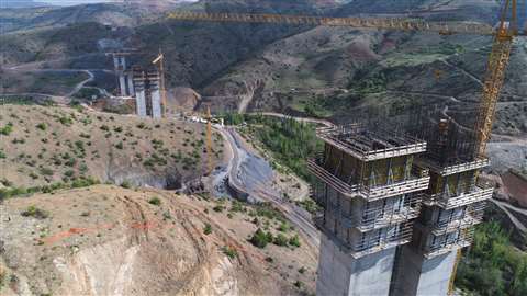
At 1,372m in length, the viaduct will span the Göksu River to link Central Anatolia with Turkey’s Mediterranean region. In its construction, a total of 130,000m³ of concrete and more than 25,000 tonnes of steel will be used.
CSiBridge software was used to model the viaduct in 3D so that the bridge’s ability to handle vertical and lateral forces could be assessed and the results incorporated into its planning.
The simulations indicated that the shortest pier, at 31m, would be most affected by seismic forces, while the long bridge deck and the tallest pier, at 155m, would be more susceptible to creep, shrinkage and temperature effects, as well as wind loads.
Based on these results, only the four tallest piers are being cast monolithically with the deck sections.
The balanced cantilevering superstructure sections are being constructed by Doka towards each other from pier head to pier head. The four cantilever forming travellers (CFTs) work in pairs, to keep the horizontal forces acting on the bridge piers in equilibrium. The travellers can handle varying section lengths from 3 to 5m and concrete weights of up to 227 tonnes.
Automatic climbing
The bridge piers are being formed by six paired sets of Doka’s automatic climbing formwork Xclimb 60. The system climbs hydraulically, anchored to the structure at all times by guiding shoes, allowing it to continue climbing in windy conditions.
Work on the Eyiste Viaduct started in March 2017 and is scheduled for completion in mid-2020.
A viaduct project in the UK demonstrates how the increasing popularity of off-site construction techniques, far from marginalising falsework and formwork companies, is providing plenty of work for them – if not more. According to US-based EFCO, this is because methods for the placement and support of pre-cast units on site often require at least as much temporary work as an equivalent cast-in-place solution.
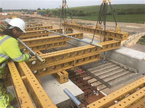
One example is the 750m-long viaduct being built over the River Great Ouse and the East Coast rail line as part of the A14 Cambridge-to-Huntington improvement project in the UK.
It features a composite deck consisting of heavy steel members with pre-cast slabs and parapet beams. The pre-cast elements are then connected to complete the deck with an in-situ stitch pour.
The challenge for EFCO was to design and supply a system of beams that could support the 6.5 tonne pre-cast units as they rested on the edge of the steel before the final stitch pour was executed.
Adding to the complexity of the job, the bridge had a tight tolerance and complex geometry. So, EFCO’s solution required suitable adjustment in all three axes at the key setting out locations, and the beams had to be pre-set to allow for a calculated deflection under load once the crane was released.
Working in close collaboration with the project’s contractor and sub-contractor during planning, EFCO developed a two-stage approach.
Adjustable members
First, adjustable beam members were provided and attached to the pre-cast units before they were transported to the project site. The beams had fine-adjustment threaded units that allowed for each member to be set to the correct angle before being lifted into position on the bridge. At the same time, twin support beam members were attached to the pre-cast slab on the bridge deck and adjusted to provide accurate bearing locations for the landed units.
Once each unit was placed, the crane was released and checks were made on the accurate final position of the pre-cast concrete. The support members then remained in place until the reinforcement for the stitch pour had been placed, the concrete pumped and adequate strength achieved for the structure to be fully self-supporting.
In total, 252 pre-cast units weighing a total of 1,638 tonnes were placed on the bridge using 40 sets of support beam assemblies that were re-used and adjusted for geometry as they cycled down the structure.
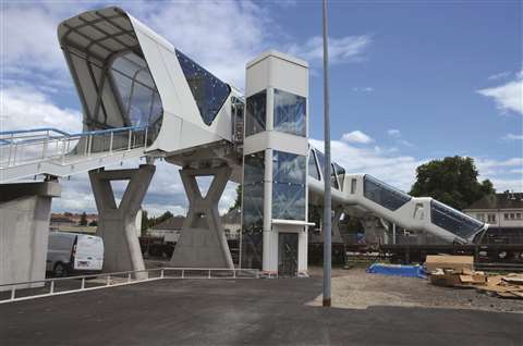
A reinforced concrete footbridge was recently constructed at the Haguenau railway station in France using formwork from Paschal.
The 98m-long bridge has four piers and two abutments. To support the concrete piers and absorb loads safely and steadily, French contractor Eiffage used 18m² of Paschal’s Modular universal formwork to form the foundations for the piers.
The pier foundations had a thickness of between 0.6 and 1m, and they were constructed on bored piles that went to a depth of between 10 and 15m.
The universal formwork is based on a modular design concept by Paschal and it was said to minimise the need for on-site adaptations.
Paschal’s large LOGO.3 formwork system was used not only for the piers but also for the construction of the two abutments with integrated engineering rooms, in conjunction with Modular universal formwork, demonstrating the versatility of the two systems.
A recent project to restore the Ágora building of the Palace of Sciences and Arts in Valencia, Spain, demonstrates how digital technology can help with the process. Ulma used building information modelling (BIM) to tackle the structure’s unusual elliptical geometry.
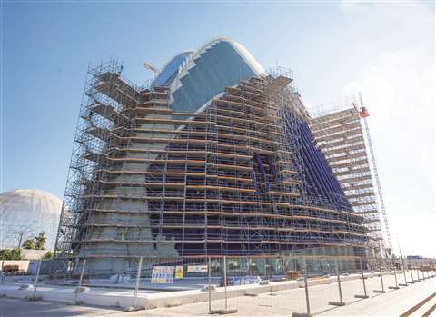
The entire building was covered with multidirectional Brio scaffolding to refurbish more than 4,247m2 of space, both externally and internally.
BIM technology was used to help the various collaborators interact effectively. It allowed Ulma to plan each section and register them all in a single place that was accessible to all parties.
Cantilevered extensions
For the north and south ends of the building, Brio Perimeter scaffolding with one-metre cantilevered extensions was used to reach a maximum height of 33m and cover a total surface area of 1,000m2.
For the four central phases of the building, which stretch to a height of 48m and have a surface area of 2,600m2, the same Brio Perimeter scaffolding was used but with cantilevers that extended up to 3m and push-pull props that were adjusted to adapt the scaffolding precisely to the building’s varied curvature.
Digital planning was also used by Layher in a Swedish sugar factor project recently. A concrete silo with a height of 69m and a capacity of up to 80,000 tonnes of sugar was built by German contractor Heitkamp Bauservice using the slip-form method.
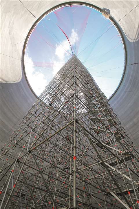
The silo wall grew at a rate of 2.5m per day, but a particularly challenging part was the roof structure, which consisted of roof rafters and a steel compression ring as the top closure element at a height of 63m. When the individual components were not forming a closed structure, the 45-tonne mass required high-strength support.
3D designs
Applications engineers from Layher helped to plan a solution using the company’s software LayPLAN, which includes a CAD module. This plug-in for Autodesk AutoCAD can be used to create 3D designs of all types of scaffolding structures.
The solution used in this scenario included three of Layher’s systems – Allround Scaffolding Lightweight, Allround Shoring Frames TG 60 and pre-assembled Allround Shoring Towers TG 50.
It is important to keep on-site inventory to a minimum for reasons of efficiency and safety. This was certainly the case on a recent project to construct a commercial building for retail, warehousing and offices in Austria, on behalf of the company Spiral Reihs & Co.
Meva’s MevaDec solution was used for the creation of the four-storey building with slab areas of 2,000m² on each level and numerous columns, as well as the installation of collective safeguards.
The flat slabs for the new office building were supported by columns with drop panels. The columns themselves were first cast using Meva‘s Mammut 350 wall formwork.
While the 3.5m panel heights eliminated the need for any vertical extension, the 100kN/m²
fresh concrete load capacity allowed unlimited pour speeds for casting up to this height, which was said to accelerate progress.
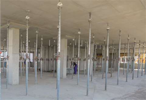
The MevaDec slab formwork was then assembled around the columns. Its grid-free assembly allowed it to be adjusted to the required geometries, minimising filler areas. Continuous adaptation to different layouts could be achieved by simply changing the assembly direction of the primary beams.
A key feature of the system was said to be its pre-defined prop grid, which minimises the number of props required and thereby helps to reduce the quantity of material needed on site.
Safety is of course an important concern too, and under the Austrian Regulation on the Protection of Construction Workers, suitable guard railings were required for elevated work locations at heights of more than 2m.
However, at the same time, it was important that these collective safeguards did not obstruct the works. This is where Meva’s versatile stop-end brackets, stop-end rails and shoes came in useful because they could be fixed in a variety of ways to prevent the safety mesh from posing a hindrance.