Keeping it smooth
28 February 2008
A common problem associated with wire rope is snagging on the winch drum, when an outer layer becomes trapped between wraps of underlying rope. Another common problem is damage to the lower layers caused by crushing from outer layers. With multiple layers of rope on a drum, the pressure on lower layers is immense.
In offshore applications, huge lengths of rope are often housed on drums. The anchor winches on Saipem's Semac 1 pipe laying barge, for example, each hold 2,800 m of 76 mm diameter wire rope in 14 layers. It is bad enough having wire rope problems on a crane on a construction site, with the resulting replacement cost and lost time. Working offshore, though, the costs of rope or winching problems are huge.
The secret to avoiding problems, whatever the application, is to get the right drum. This means having it specially designed to specifically match the structure and length of the wire rope to be used.
Grooving on the face of the drum is commonly used to ensure that the rope spools smoothly and tidily. Where there is just a single layer of rope on the drum, a single helical groove, like the thread of a screw, will ensure the rope travels smoothly across the drum during spooling operations.
In multi-layer applications, however, a helical groove will result in additional layers of rope lying at an angle to lower layers, crosswise, and so risk crushing lower layers. This is where Lebus grooving comes into its own. It is a special grooving pattern developed in the 1950s by Frank LeBus, an American who supplied equipment to oilfields. In 1937 he had patented the use of a groove bar to guide the spooling of rope on hoist drums and later refined this to become what he called the LeBus Counterbalanced Spooling System. Though some companies have sought to imitate the Lebus system, the original is only produced by Lebus companies in the USA, Germany and the UK.
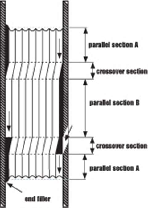
The Lebus grooving pattern has the grooves parallel to each other, and parallel to the flanges of the drum, with a crossover point on every groove on each side of the drum, (Figure 1). With this pattern, when the first layer has filled the drum, the second layer then travels back across the drum with each wrap of rope sitting precisely along the groove of two wraps of the first layer, (Figure 2).
With Lebus grooving it is possible to calculate the exact forces that the rope imposes on the drum because the spooling is totally controlled. This is not possible with any other spooling system.
Cross winding is reduced to approximately 20% of the circumference of the drum, and 80% remains parallel to the flanges in the inner layer rope groove.
This parallel grooving evenly distributes the load between the individual layers and has been shown to increase substantially – by more than 500% – tests have shown, the life of the wire rope.
This very rapidly repays any extra up-front cost and results in massive lifetime cost savings, especially in applications where downtime is costly, be that oil production or critical-path construction.
To maximise the benefits of the Lebus grooving system, however, certain operating conditions are required. These are outlined below.
Application-specific design
Every Lebus system must be custom engineered. It is designed and produced specifically to meet the application for which it is used. The groove pattern is engineered to suit the rope's length, diameter and construction type.
Spool under tension
In any multi-layer spooling application it is important that when the rope is first installed on the drum, it is done so under tension to avoid any slack on inner layers that can be crushed or nicked against the groove walls by outer layers.
In general, the tighter the line, the better the spooling, but the rope should be tensioned with at least 2% of the breaking load or 10% of the working load. However, provision must also be made for the safety coefficient and the design of the cable. All subsequent spooling should also take place with the line under tension.
Correct fleet angle
The fleet angle is the angle between the rope coming off the drum and the point at which it meets the first fixed sheave. Optimum fleet angle depends on the load, wire rope construction and line speed but our unrivalled experience has taught us that, as a good rule of thumb, it should generally never be any more than 1.5 degrees and no less than 0.5 degrees. Using these fleet angle guidelines means that for every 10 m that the drum is distanced from the sheave, the rope's distance from the midpoint of the drum should never be more than 260 mm (520 mm between the flanges).
With helical grooved drums, the fleet angle can be up to 3 degrees, since the grooving is already at an angle to the flange, but only if the rope is wrapped in a single layer. If there is a second layer, such a large fleet angle will result in the rope cutting across too much and leaving gaps, which damages the rope.
Fleet angle compensator devices are available for applications that do not meet the necessary parameters but do require smooth multi-layer spooling.
Correct D:d ratio
The ratio between the diameter of the winch drum and the diameter of the wire rope, which is expressed as D:d, should be greater than 25:1.
Correct wire rope specification
When spooling a wire rope around a drum in multiple layers, the rope needs to be flexible enough to wrap tightly onto the drum, yet also sturdy, strong and rigid enough so that it does not suffer any deformation. Lebus has worked closely with all the major international wire rope manufacturers in developing optimum specifications for multi-layer applications.
Follow these guidelines and you can be sure of problem-free smooth spooling, without interruption to your operations.