Massive movers
25 April 2008
James Verrinder reports on some of the largest and most spectacular heavy lifting jobs from around the world over the last year
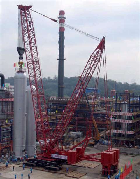
A Manitowoc Model 21000 crawler crane, owned by Chinese oil major Sinopec, has completed its largest lift as part of reconstruction work taking place at the Beijing Yansan Petrochemical Complex close to the city of Zhoukoudian, China. The crane positioned an 812 tonne (895 US ton) hydrogenation cracking unit, a component used to process industrial oil.
Renovation work to expand the production capability at the petrochemical complex began in March this year. The Model 21000 arrived on site in May after traveling 700 km (435 miles) from its base at the Sinopec #10 yard in Shandong to the refinery south of the Chinese capital. Since arriving on the job, the crane has served as the main apparatus for all major material handling.
The crane was fitted with a capacity-enhancing Max-Er attachment for the cracking unit lift, boosting the maximum capacity to 907 tonnes (1,000 tons). Main boom on the lift was 54 m. The whole process, from picking the vessel to final positioning, took less than 30 minutes.
Ma Zengtao, manager of Sinopec’s crane fleet, said he was impressed with the ease of operation and extra capability the Max-Er attachment offers. “The lift went ahead without a single glitch,” he said. “The Model 21000 worked so effortlessly it made lifting the cracking unit look easy and gave us great confidence. We invited senior management from refineries around China to see this lift and it was certainly a credit to Manitowoc and the ingenuity of its engineers. The Max-Er attracted a great deal of interest and has proven a worthwhile investment on top of the Model 21000.”
The hydrogenation cracking unit, which measured 4.6 m in diameter and was 35 m tall, processes industrial oil, turning it into gasoline and kerosene. It is capable of a throughput of some 10 million tonnes of fuel per year and its installation is the single most important element of the reconstruction work.
Tandem demolition
Several large cranes were needed to dismantle a two-lane arched bridge on the A8 motorway at Gersthofen/Augsburg in Germany. The six cranes, a mixture of Liebherr crawler and wheeled mobile units, were owned by rental houses Riga/Baumann, Felbermayr, Schmidbauer KG and Weiland and were working for demolition firm Max Wild.
To lift out the giant steel bridges, each one about 90 m in length and weighing 500 tonnes, two Liebherr LR 1750 crawler cranes were supplied by Riga/Baumann and Felbermayr. With the holiday traffic in full flow, the two cranes were set up on either side of the River Lech. Each crane was rigged with a 56 m main boom and a 31.5 m derricking jib.
It was not possible to roughly calculate the weight of the bridges so a test lift of the entire bridge was carried out first, which showed a total load of almost 500 tonnes as soon as the bridge was removed from its bearings. This meant that each crane had to lift an overall weight of 248 tonnes at a working radius of 30 m.
Working with cutting torches from their caged platform, it took the demolition engineers from Max Wild two hours to break the 60-year-old arched bridge in two. The men were lifted from the bank and held over the centre of the river by Weiland’s LTM 1250-6.1 and an LTM 1160/1 from Schmidbauer KG.
Once the demolition engineers had finished cutting, the two halves broke apart and the two crawlers each reversed away carrying a section each and lowered them so they could be transported away. Both cranes were then driven back into position, ready for the demolition of the second motorway bridge the following day.
In total, 20 engineers from the participating crane companies were involved in this project. Sophisticated wiring enabled ongoing readings of cable forces as it was not possible to predict exactly where the centre of gravity after being broken in two, so that the individual bridge halves could have been restored to a horizontal position if necessary.
Building a bridge
In the US, Bigge Crane & Rigging, of San Leandro, California has installed the second of a pair of 2,000 ton (1,814 tonne) steel bridge deck sections on the new San Francisco Oakland Bay Bridge.
This second mega-lift operation completes the transition spans between the concrete Skyway bridge on the Oakland side and a suspension bridge – not yet built – to Yerba Buena Island.
The first transition span, carrying the eastbound carriageway, was lifted into place overnight in February this year. The second span, which will carry westbound traffic, was completed in an overnight operation in August.
Each transition span section – called tubs – was lifted to a height of approximately 200 feet (61 m) within tolerances of 1/32 of an inch (0.8 mm). To lift such a heavy weight precisely, Bigge used computer-controlled Hydrospex strand jacks.
For each lift, the strand jacks raise the load at speeds of up to 30 feet (9 m) per hour. During the lifts, the tubs were maintained with an eighth of an inch of the required attitude. Given that the tubs are 200 feet long by 85 feet (60 m x 25 m) wide, computerised monitoring was essential.
At the Oakland side (to the east), where the Skyway bridge deck has already been constructed, four strand jacks, each with a 365 ton (331 tonne) lifting capacity, were mounted on a mobile jacking platform supported by a pair of 60 foot (18 m) girders, cantilevered 28 feet (8.5 m) off the bridge deck.
At the San Francisco side (to the west), main contracting consortium Kiewit-FCI-Manson constructed two steel lifting towers, founded on piles driven into the Bay for this purpose. Bigge supplied the two girders that span 125 feet across the top of this lifting tower as well as six 235 ton capacity strand jacks mounted on top of a mobile jacking platform that sits on these girders.
All of the jacks were synchronized for simultaneous operation and load control within 1/32 inch (0.8 mm).
Each tub was lifted from a barge that Bigge had used to transport them from Portland, Oregon, where they had been fabricated. For each of the transport operations, Bigge loaded the tub onto the barge using 48 axle lines of Scheuerle self- propelled modular transporter (SPMT). With bridge piers, erection towers and other obstacles, there was no space to bring in the barge at the correct angle under the bridge. Instead, Bigge was able to rotate the barge-mounted SPMT to turn the tub by the necessary 90 degrees.
As on the first lift, now the second tub is raised to its final elevation, a temporary support tower has been skidded under it at the Oakland (east) end of it to hold it in place for three months until the concrete joint with the existing Skyway is poured and cured, filling a gap of some 6 feet (1.8 m). The San Francisco (west) end of the tub is being supported by another temporary tower until the suspension bridge is constructed.
“To lift a 2,000 ton load that is 200 feet long and 85 feet wide to a height of 200 foot is an operation that requires precise engineering and thorough planning,” says Weston Settlemier, president of Bigge Crane & Rigging. “To do it twice is something special for us,” he adds.
“As a local company we are very proud to have made such a contribution to this project. My grandfather Henry Bigge, who founded this company 90 years ago, hauled the steel that built the Golden Gate bridge in the 1930s. I am delighted that the tradition of Bigge’s involvement in the construction of iconic structures in the Bay area continues today.”
The New Bay Bridge is expected to cost $6.3 billion and be completed in 2012.
Module installation
ALE Megatranz recently completed the installation of the M5 living quarters module for the PRA-1 project, Brazil. Before starting the lift operation, the M5 module was moved by skidding from the assembly area to the lift position.
The module, which weighed 1,350 tonnes was lifted 25 m above the M3 Deck using two pairs of lifting gantries which were installed for the lift. The front gantries were placed each side of a lifting beam close to the M3 module. The rear gantries were placed directly above the rear lifting point of the lift beam. The front gantries each had two 500 tonne capacity HLS5000 strand jacks installed on the top of each lift tower. The rear gantries each had one HLS5000 lifting unit installed at the top. After the module was lifted above the M3 Deck, the module was then skidded 22 m longitudinally using sixteen 150 tonne capacity skid shoes.
The lifting operation was completed in five hours using the fully computerised new design heavy lift system recently acquired by ALE. •