Tech Corner: Hot oil carry-over problems
26 July 2021
A study, backed up by calculated and experimental results from Dr Abdelhakim Laabid and Thilo Koch, investigates how the reduction of hot oil carry-over in high speed running turbo application bearings can prove beneficial
Tilting pad journal bearings are used in turbo machines like turbo compressors, turbo gears, gas turbines and steam turbines. By increasing the power density, the applied loads and velocities have been increased simultaneously over the last decades.
To overcome conservative operation limits it is helpful to reduce the oil film temperatures by certain design modifications. These certain design measures are taken to prevent large parts of the hot oil coming out of one pad to reach the next pad, so that the fresh cold and hot oil are mixed as little as possible.
The focus of the article is to show these improvements. The concept of combining simulation and calculation can evaluate the oil supply efficiency and enables the designer to optimize both, the oil drainage and injection.
Limits of operating conditions
Tilting pad bearings are usually used in high speed running rotors and perform with higher stability compared to multi-lobe bearings and better oil distribution in the loaded area than flooded bearings. The limitations with respect to load and speed are given by the minimum lubrication film thickness and the maximum temperature of oil film and tilting pad surface.
The maximum surface temperature rises over a non-allowable value (eg 130°C) when both specific load and speed are increased (far) above the mentioned values (see Figure 1).
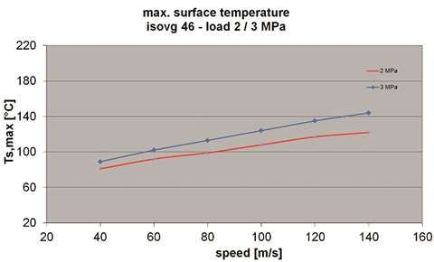 Figure 1 – Example for increase of maximum surface temperature of sliding pad related to circumferential speed
A significant reduction of the maximum pad temperature is one important option to reduce the bearing and subsequently the shaft size of the rotor, if other boundary conditions like rotor masses and natural frequencies will allow such a measure.
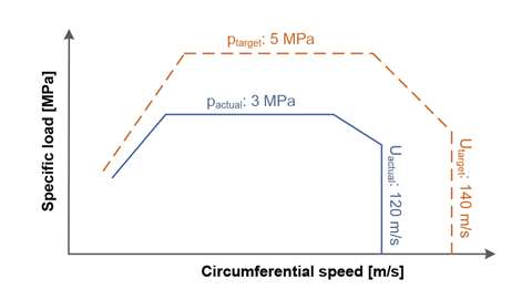 Figure 2 – Combination of specific load and circumferential speed of a tilting pad bearing application, usual limits may be shifted in future applications
Options for optimization
It is common practice to accommodate design features to the present application. There are geometric options, such as:
- Size of diameter and width;
- Number of pads;
- Geometry of pads, and;
- Other geometric parameters.
Also there are the oil supply measures to be considered as follows:
- Amount of oil;
- Design of lubrication nozzles;
- Distance of nozzles to the shaft;
- Number of nozzles, and;
- Oil pressure.
There are many possibilities to optimize the oil supply in a tilting pad bearing. For instance, an increase in efficiency is achieved by supplying more cool oil, or when cool oil is led to the highest loaded area or the hottest spots of the bearing. In addition, hot oil can be prevented from entering the gap between the subsequent tilting pad and the shaft.
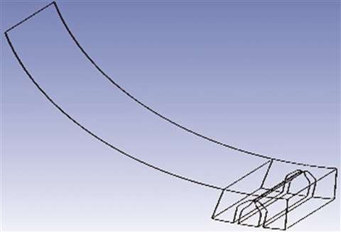
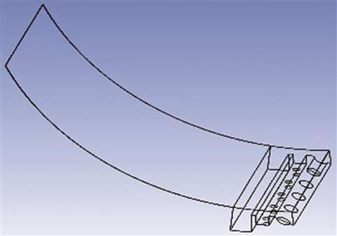
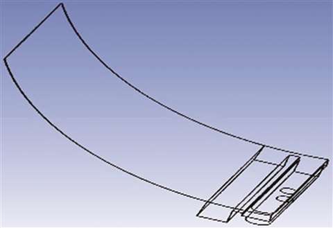
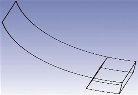
The four diagrams serve as an example, representing different design options of an oil supply unit. E0 – Simple oil supply (flooded lubrication). E1 – Supply unit with dam and tank. E2 – Supply unit consisting of oil drainage, dams and oil injections. E3 – Supply unit consisting of dam and longitudinal slit.
 E3 – Dam and longitudinal slit
 E2 – Oil drainage, dams and injections
 E1 – Supply unit with dam and tank
 E0 – Different units for oil supply
Investigating common and future design options
We began the simulation with figure E0 and progressed through the features E1, E2 and E3.
To verify the efficiency of several design elements the usual technique is to run such bearings in radial test rigs before starting a field test or even run them in a real application.
A rather modern approach is the investigation of the three-dimensional oil flow by using CFX technology (see also outputs of ANSYS CFX software in Figure 3 and Figure 4). This method is a useful tool to select the most promising design features before executing time-consuming test rig runs.
As the following example (Figure 3 and Figure 4) shows the effect on bearing temperature and oil pressure can be simulated:
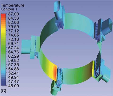 Figure 4 - CFX simulation shows oil supply pocket
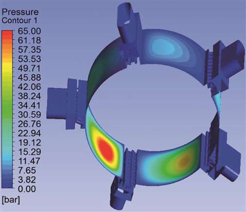 Figure 3 - Distribution of temperature and oil pressure
Investigating on new design options E1 to E3, for example, each pad has at least one hot oil drainage disposed in the space between two tilting pads.
The first hot oil drainage replaces known oil injections, which can be placed in spaces between the tilting pads. Moreover, by using a hot oil drainage the space between the two adjacent tilting pads is filled so that the occurrence of a large oil supply in that area is hindered.
Furthermore, a first dam and an oil injection, which is directly located behind the first dam, could be included in the design. The added oil jet splashes oil onto the shaft to spray-wash the thin layer of hot oil off the shaft.
By means of the oil injection the last residual oil on the shaft, which is dragged over from the previous lubrication gap, is broken and detached from the shaft. It then forms a mixture with the freshly supplied oil.
Since a portion of the warm oil was already intercepted by the first dam, the detached hot oil from the shaft contributes to the mixture. The temperature of this mixture is therefore substantially determined by the temperature of the injected fresh oil.
However, the hot oil drainage also has a second oil discharge, through which a portion of the mixture from the hot oil detached from the shaft and the injected cool oil can be discharged again.
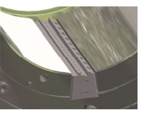 Figure 5 – Tlting-pad bearing shows space between pads filled by oil drainage, dams and oil injection unit
This has several advantages. Firstly, the portion of hot oil that comes from the previous tilting pad, is effectively prevented from entering the next lubrication gap. In addition, the oil discharge could allow more fresh oil injection.
The ratio between the injected cool oil and hot oil released from the shaft is further shifted in favor of the fresh oil. The average temperature of the mixture continues to decrease, so that a more effective cooling of the tilting pad bearing is achieved by the oil discharge.
This design of the oil discharge and drainage unit should ensure that only a very small part of the warm oil of the previous lubrication gap can enter the next lubrication gap.
This might be achieved by the combination of the various hot oil drainage components. The space between two adjacent tilting pads can almost completely be filled by the drainage unit and fluid losses can be minimized.
Using a second dam offers the option that the mixture of the injected fresh oil and the heated oil can be, at least partially discharged and is not used for lubrication within the next lubrication gap. Thus, a hot oil carry-over to the subsequent lubrication gap is almost completely prevented.
The necessary lubrication oil of the following lubricating gap is provided by the additional fresh oil supply. Subsequently, this one can work with a lower pressure. A more laminar flow of the lubricating oil into the gap can be achieved, thereby it also prevents losses caused by friction and turbulence.
The oil injector in the axial direction might contains several nozzles. By this, the oil is injected perpendicular to the shaft and the residual hot oil film on the shaft can be reliably broken and splashed off.
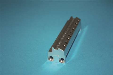 Figure 6, E2 – Unit with oil drainage, dam and injections
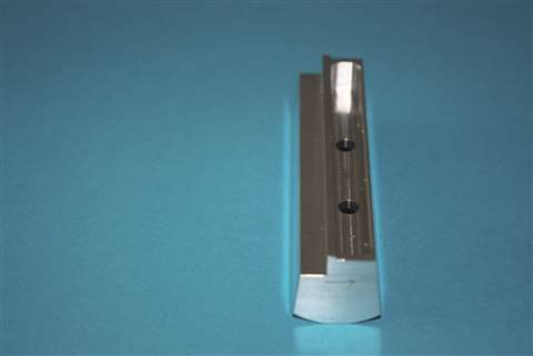 Figure 6, E-1 – Example of oil supply unit with dam and tank
Another phenomenon which can be stated by looking at the following Figure 7, is that the hot oil from the previous pad is being prevented in streaming through the gap between dam and shaft due to the back flow of the fresh oil (see Figure 7).
The advantages of design E1 can be combined with separated oil injections e.g. by means of two separated oil injections consisting of a row of nozzles.
The first oil injection represents the warm oil reduction (splashing off the hot oil) and the second represents the fresh oil supply (see Figure 8).
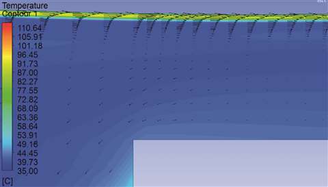 Figure 7-2 – Flow back of fresh oil between dam and shaft towards previous pad
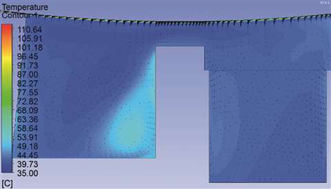 Figure 7-1 – Distribution of temperature and oil flux vectors in a unit according to design E1
Combining simulation and calculation tools
For calculating the relevant data, such as minimum film thickness or temperature of lubrication film, Miba Industrial Bearings uses a state-of-the-art software program. It has been developed by using the latest hydrodynamic theory knowledge. The model uses a finite volume method and calculates three-dimensional arrays of pressure, temperature and oil flow.
One approach in further developing the performance of any oil flow within a tilting pad bearing is to include physical results from the simulation software (eg CFX from ANSYS) and transfer it to the software calculation program.
Following, the model for the mixture of lubrication oil between adjacent pads can be optimized. The so-called warm-oil-reduction factor may be used for describing the efficiency of the oil supply. This usually depends on the operating conditions like oil viscosity, load, speed, oil supply design, oil supply pressure and others. In common industrial applications eg bearings for gas and steam turbines, the factor varies somewhere between 30-60 percent.
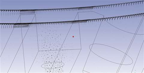 Figure 8 – Distribution of oil flow in a unit according to design E2. Separation of flow back of fresh oil by means of the first oil injection
The factor of warm oil reduction might be increased for instance by the above-mentioned design options. When looking at the results from the calculations, it can be stated that a remarkable decrease of peak temperature occurred when the warm oil reduction factor is increased from eg 30%-90%.
Conclusion
Reducing warm oil and minimizing the hot oil carry-over effect within tilting pad bearings is a powerful method to increase efficiency in high-speed running power train units.
One of the outcomes of the bearing calculations in combination with the design simulations is that the design characteristic of the oil feed unit plays a decisive role regarding the fresh and hot oil distribution, especially the number of oil nozzles and distribution thereof. Instead of using several nozzles (according to design E2) it might be advantageous under some conditions to use a kind of oil tank (according to design E1).
Furthermore, it can be stated that the concept of simulation and calculation is able to evaluate the oil supply efficiency and enables the designer to optimize both, the oil drainage and injection.
Dr Abdelhakim Laabid has been working in R&D with Miba in Germany since July 2020. Thilo Koch is also German-based and specializes in dynamic mechanical systems, vibration theory (rotor dynamics) as well as tribology (plain bearings).
Miba Industrial Bearings produces hydrodynamic bearings and labyrinth seals for use in critical centrifugal equipment, such as compressors, gear boxes, industrial pumps and turbines. It develops and produces functionally critical components along the entire energy value chain.
Their brands (Orion, Sartorius Bearings, TCE and Zollern Plain Bearings) date back to 1919, when the bearing production first started in Germany.
Miba Industrial Bearings provides a Center of Excellence in bearing analysis, design, repair, troubleshooting and reversed engineering solutions.
Click here to visit the Miba Industrial Bearings website